CD-i 210/40 switches installation
Below are some pictures from the installation of PAL/NTSC and 210/220 switches on one of my CDI 210/40 players.
Theory of operation
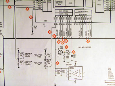
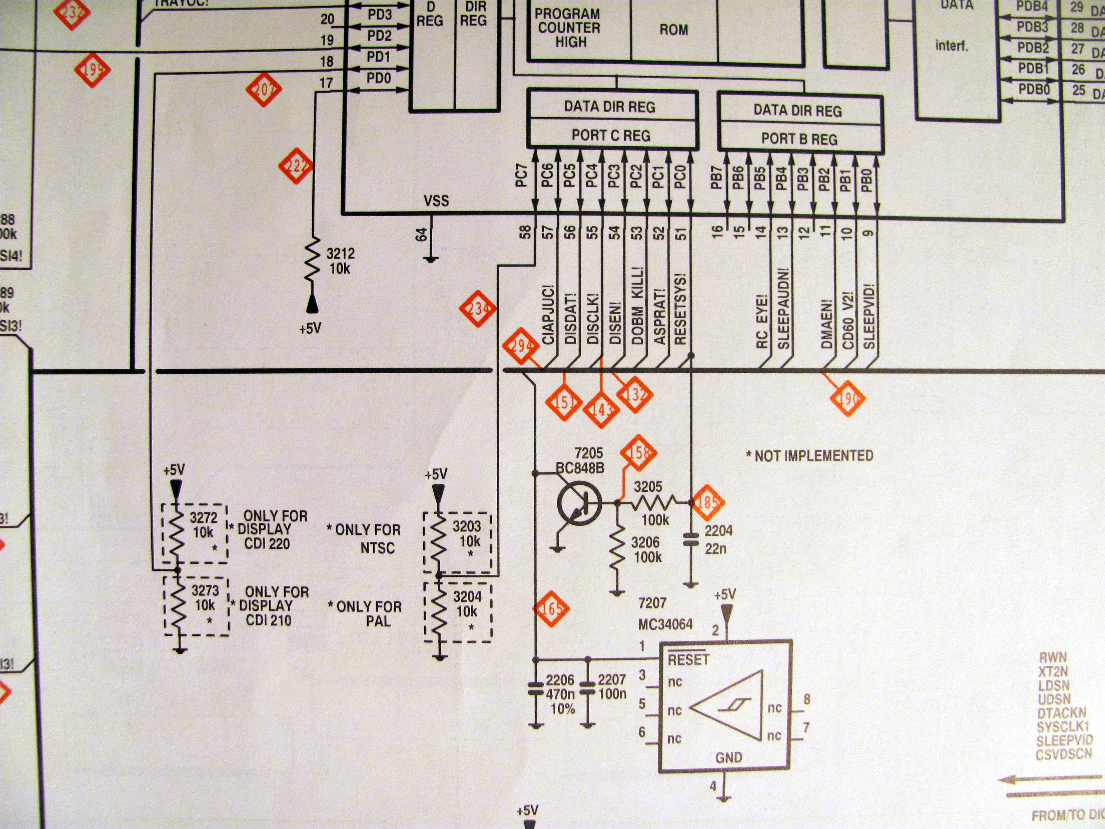
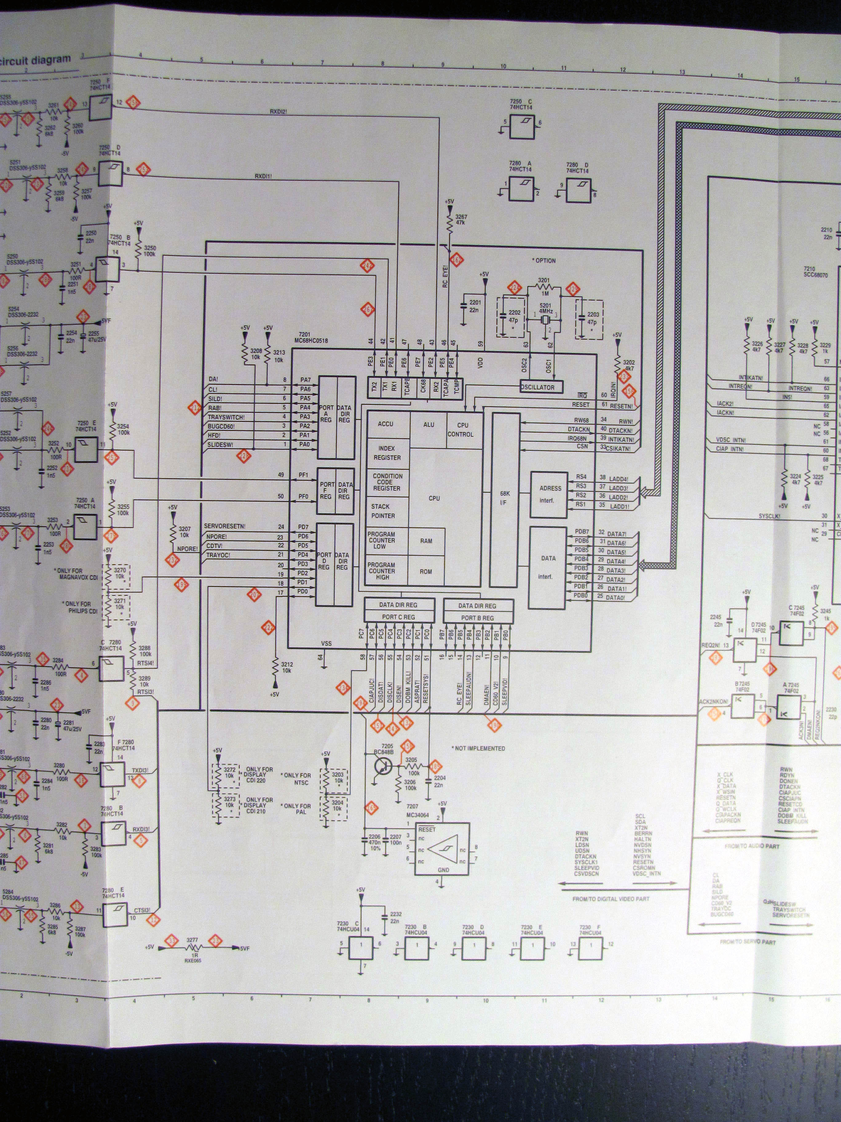
The service manual shows two sets of pullup/pulldown resistor pairs.
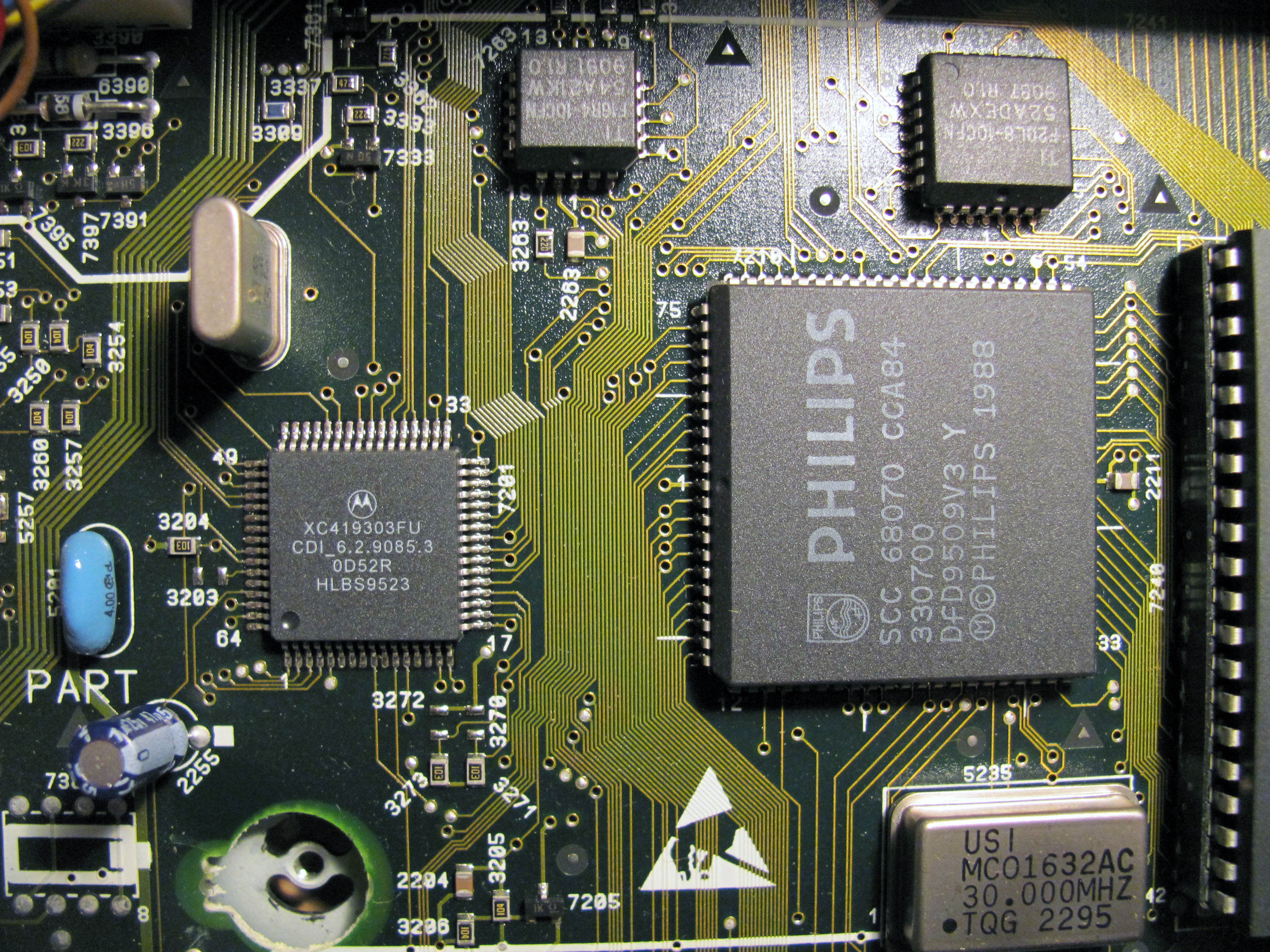
The 3272/3273 pair switches between 210/220.
The 3203/3204 pair switches between PAL/NTSC.
These resistors are connected to the IKAT processor (7201).
Preparations
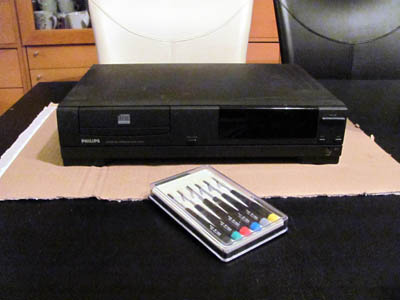
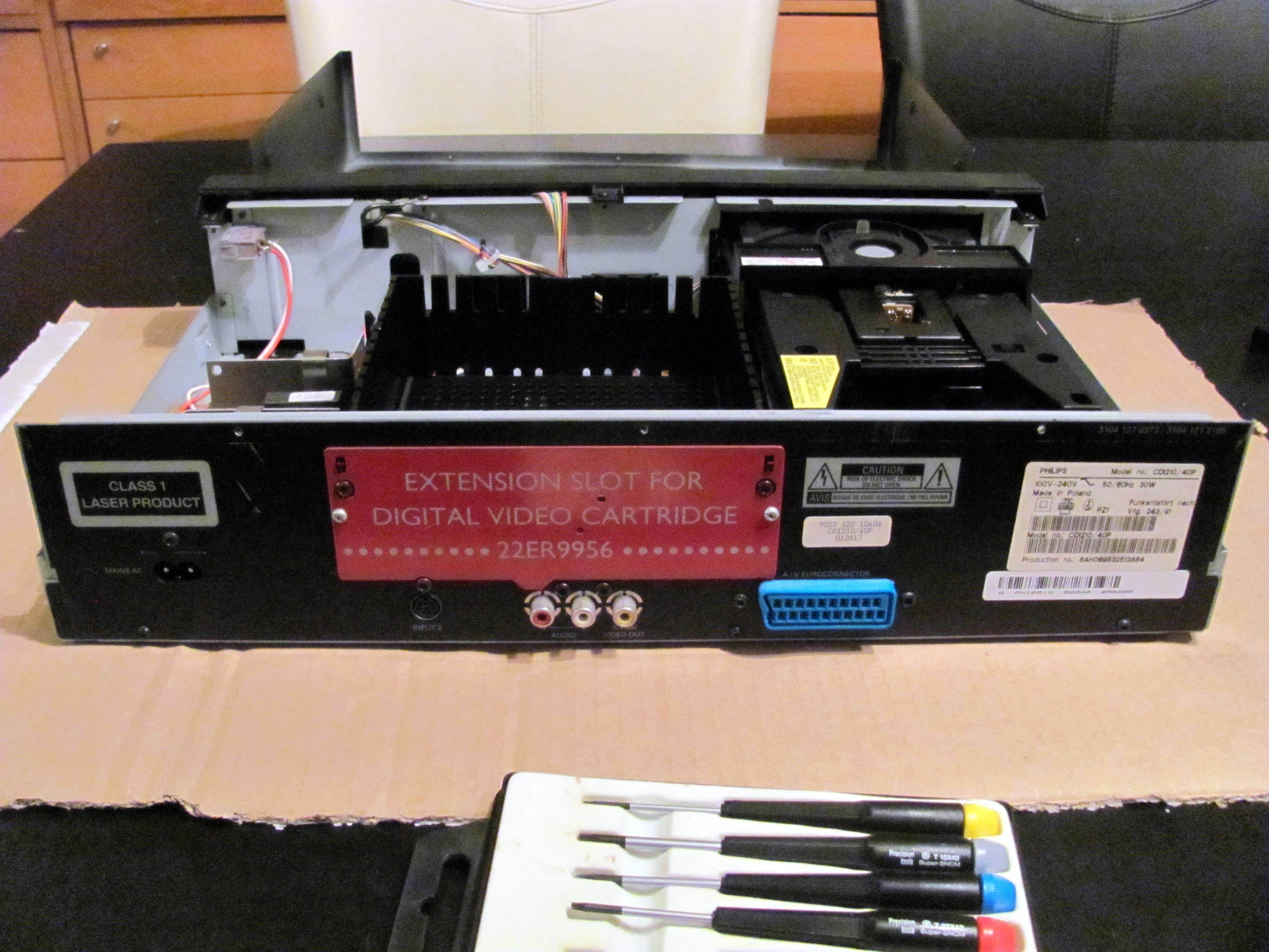
This is the 210/40 player, with a set of TORX screwdrivers.
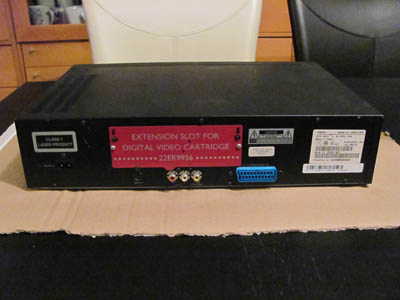
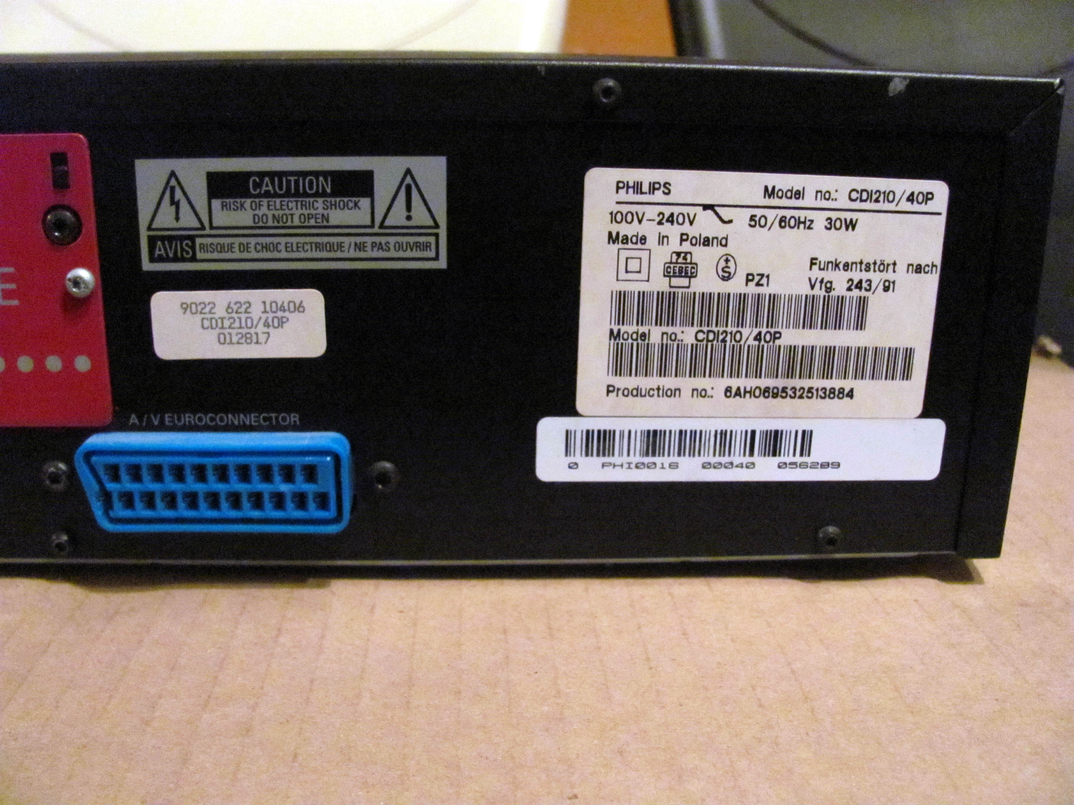
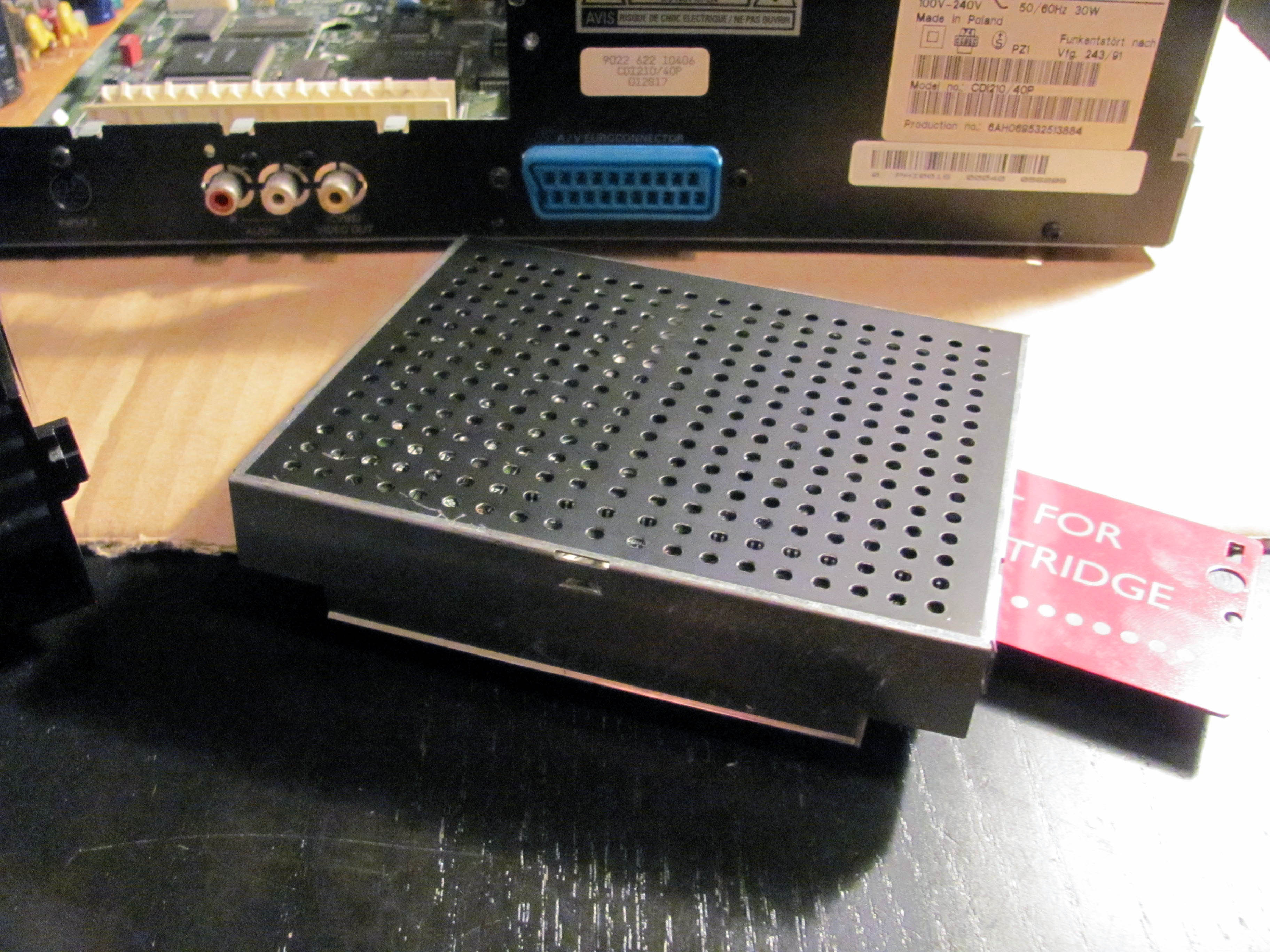
This is the backside.

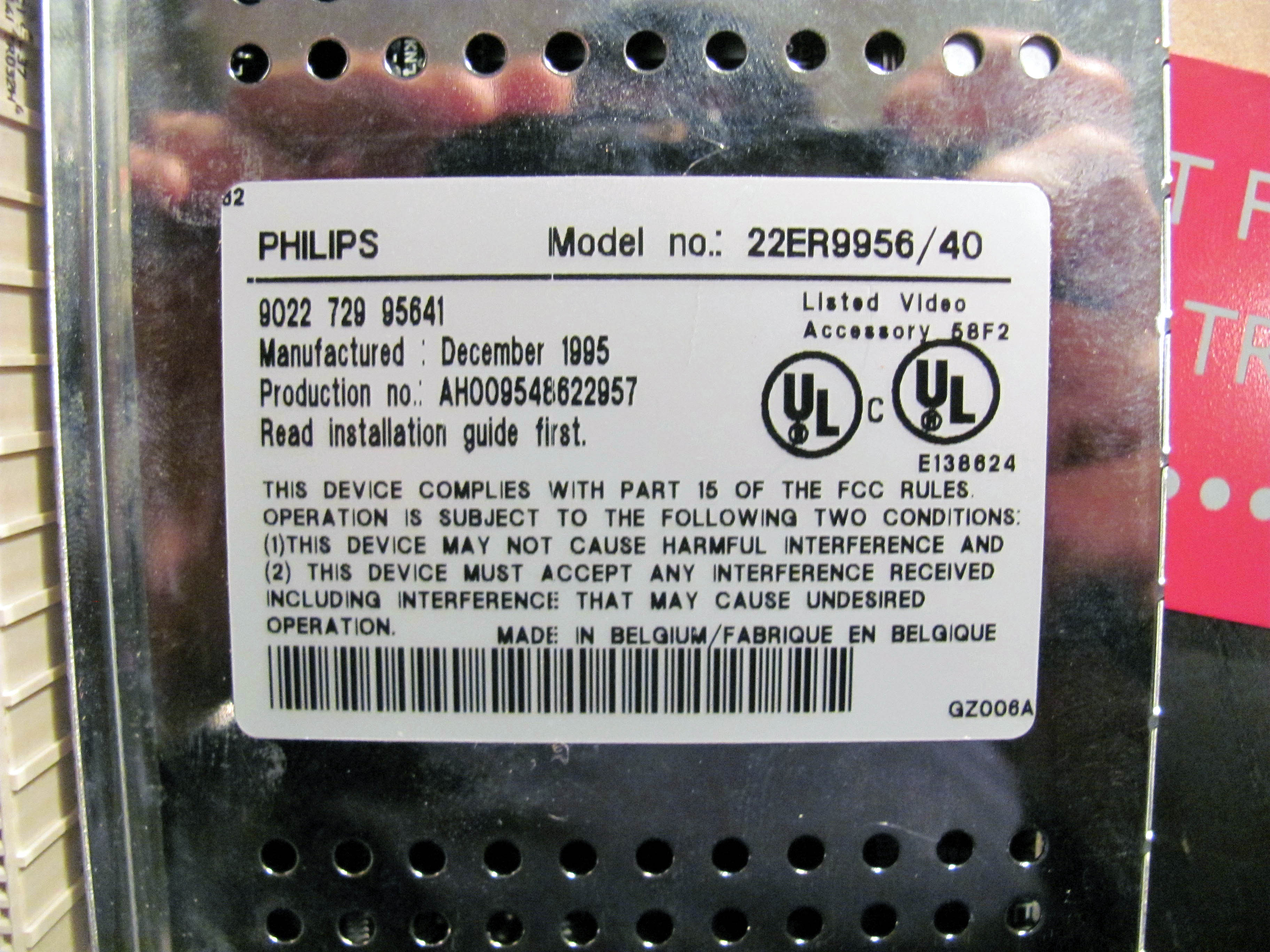
Closup of serial and manufacturing stickers.
Opening the player
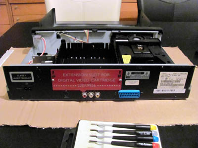
Here's the player after removing the top cover (7 TORX screws).
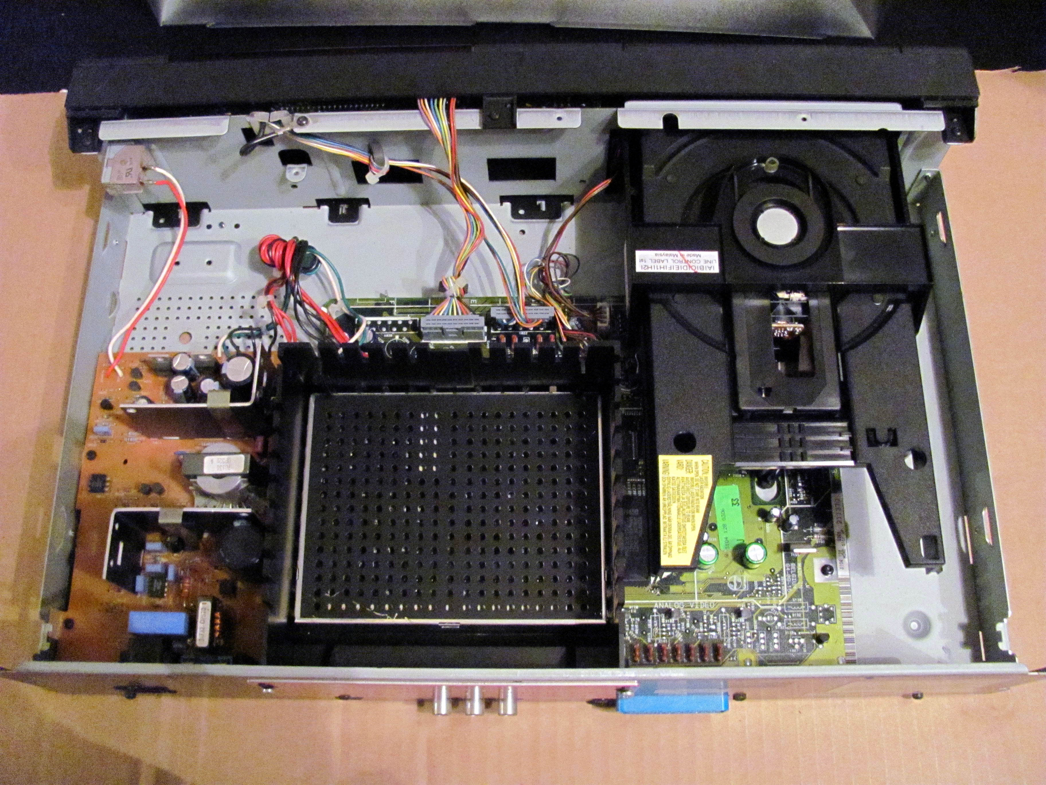
Top view of open player.
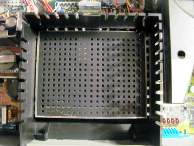
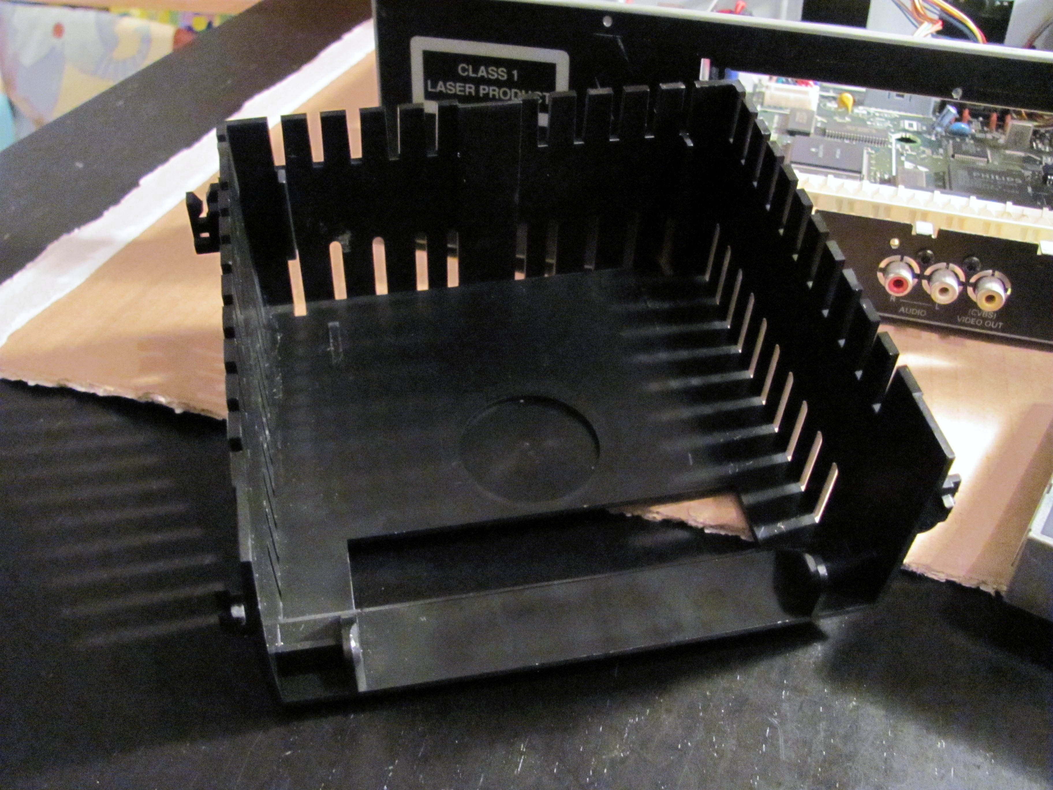
Hmm, this is in the way and will need to be removed.
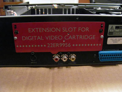
Ahh, its' the Digital Video Cartridge!
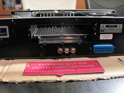
Let's remove the cover plate first (2 TORX screws).
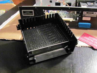
Now the DVC and its plastic encasing can be removed (3 TORX screws).
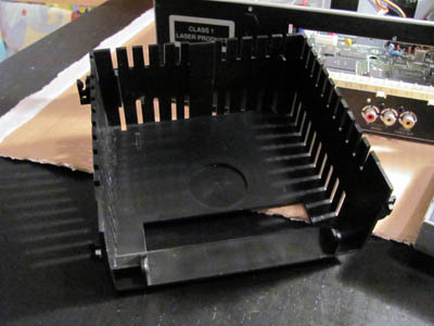
The plastic encasing is not very interesting...
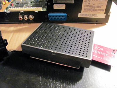
But the DVC unit might be!
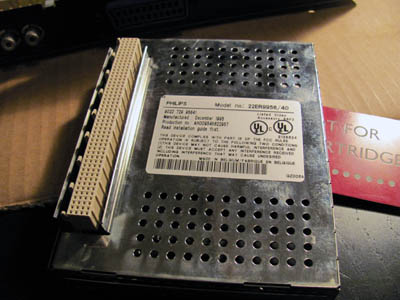
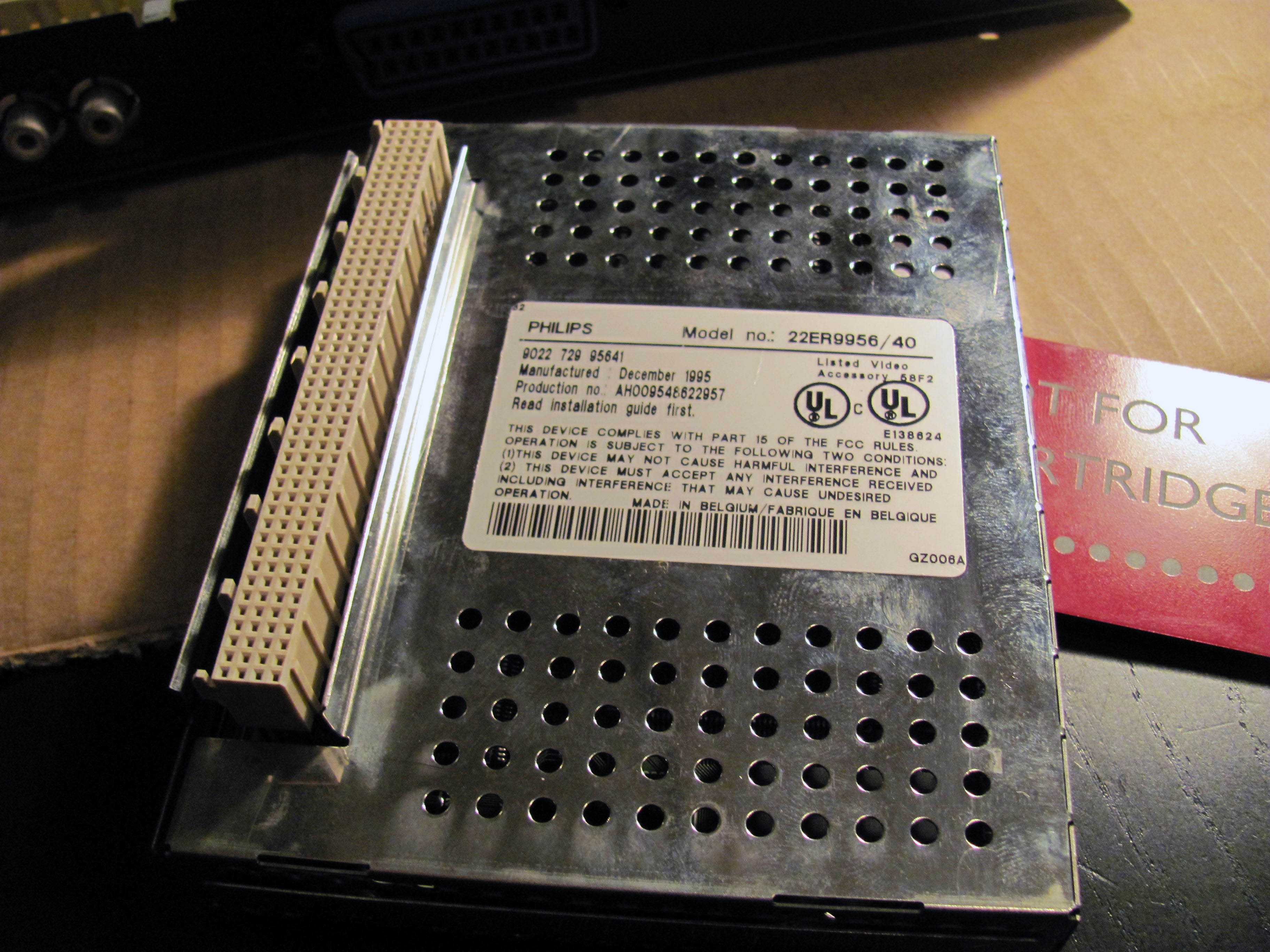
This is the underside of the DVC.
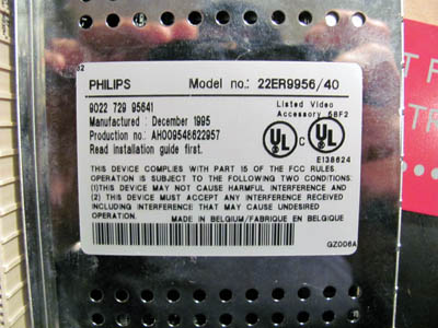
Closup of serial and manufacturing sticker.
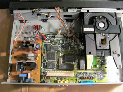
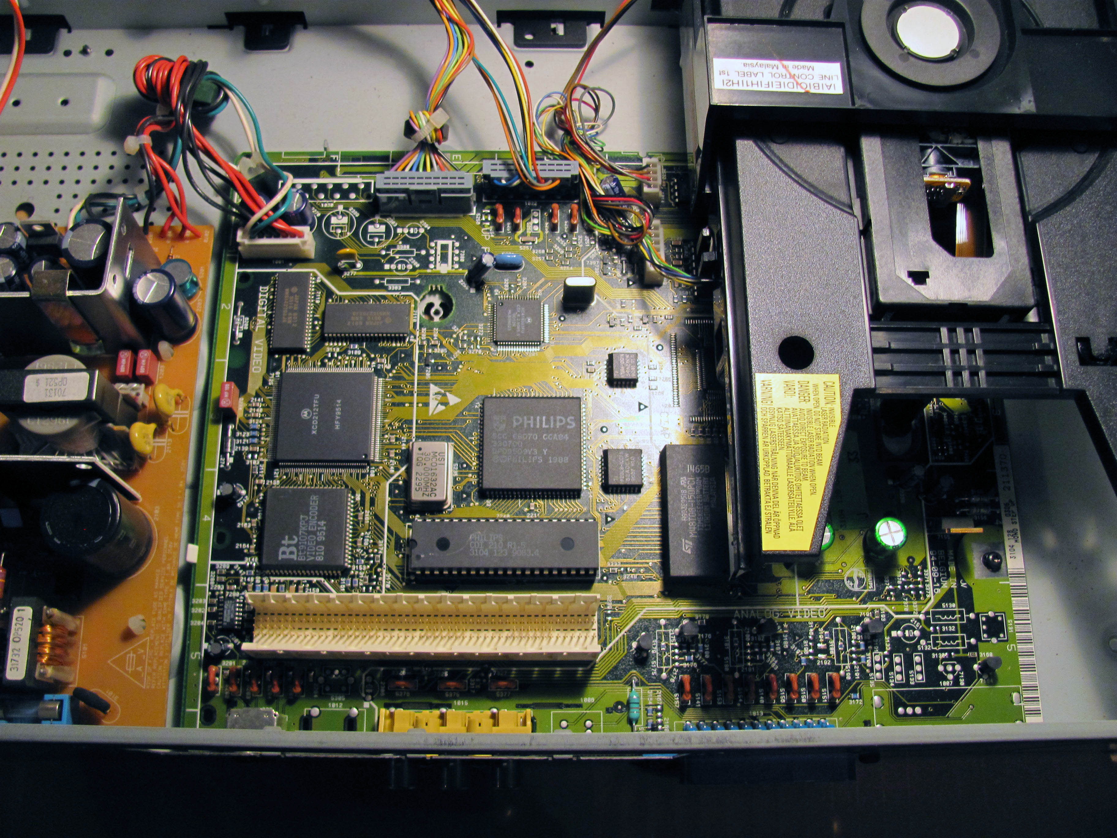
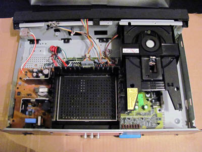
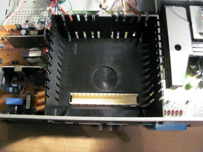
Now we have a clear view of the internals.
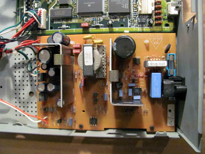
This is the power supply unit.
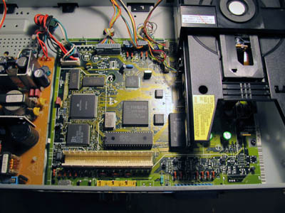
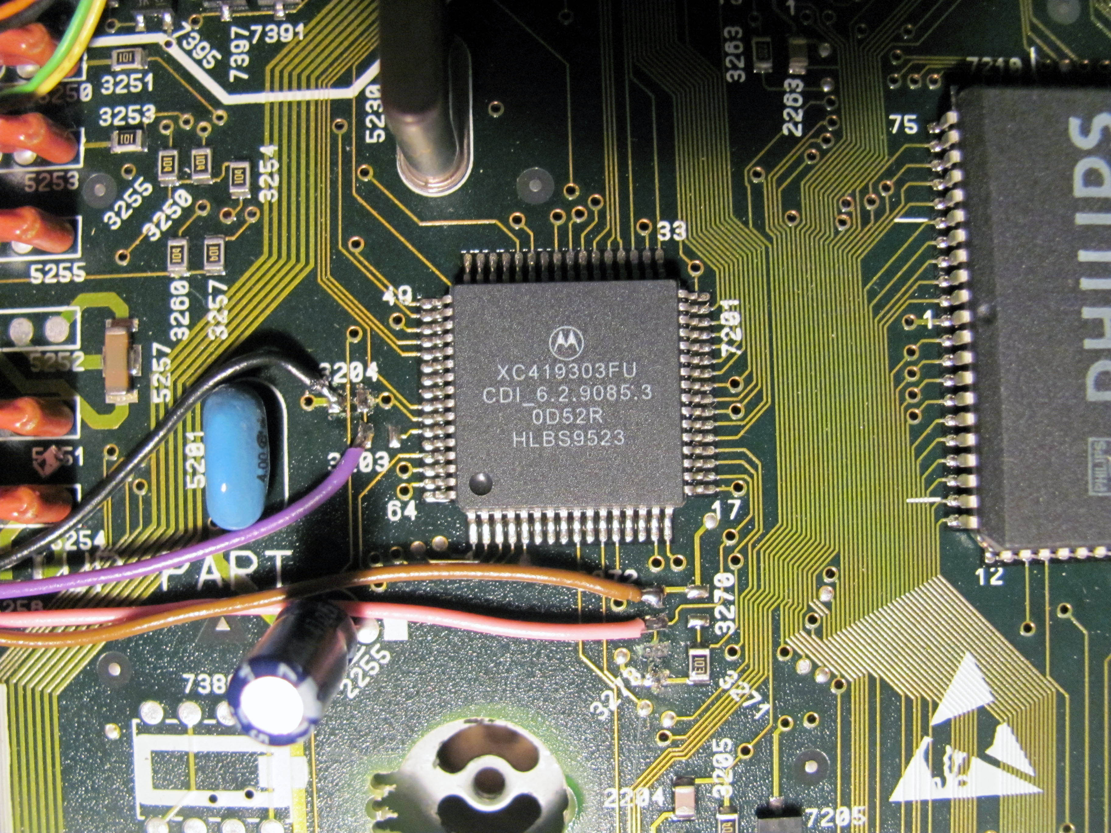
And here is the main board of the player.
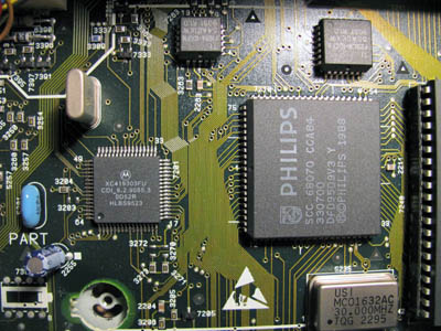
This is our target area.
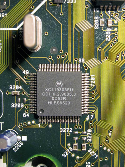
And here you can see the installed resistors and their missing counterparts.
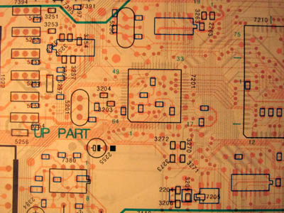
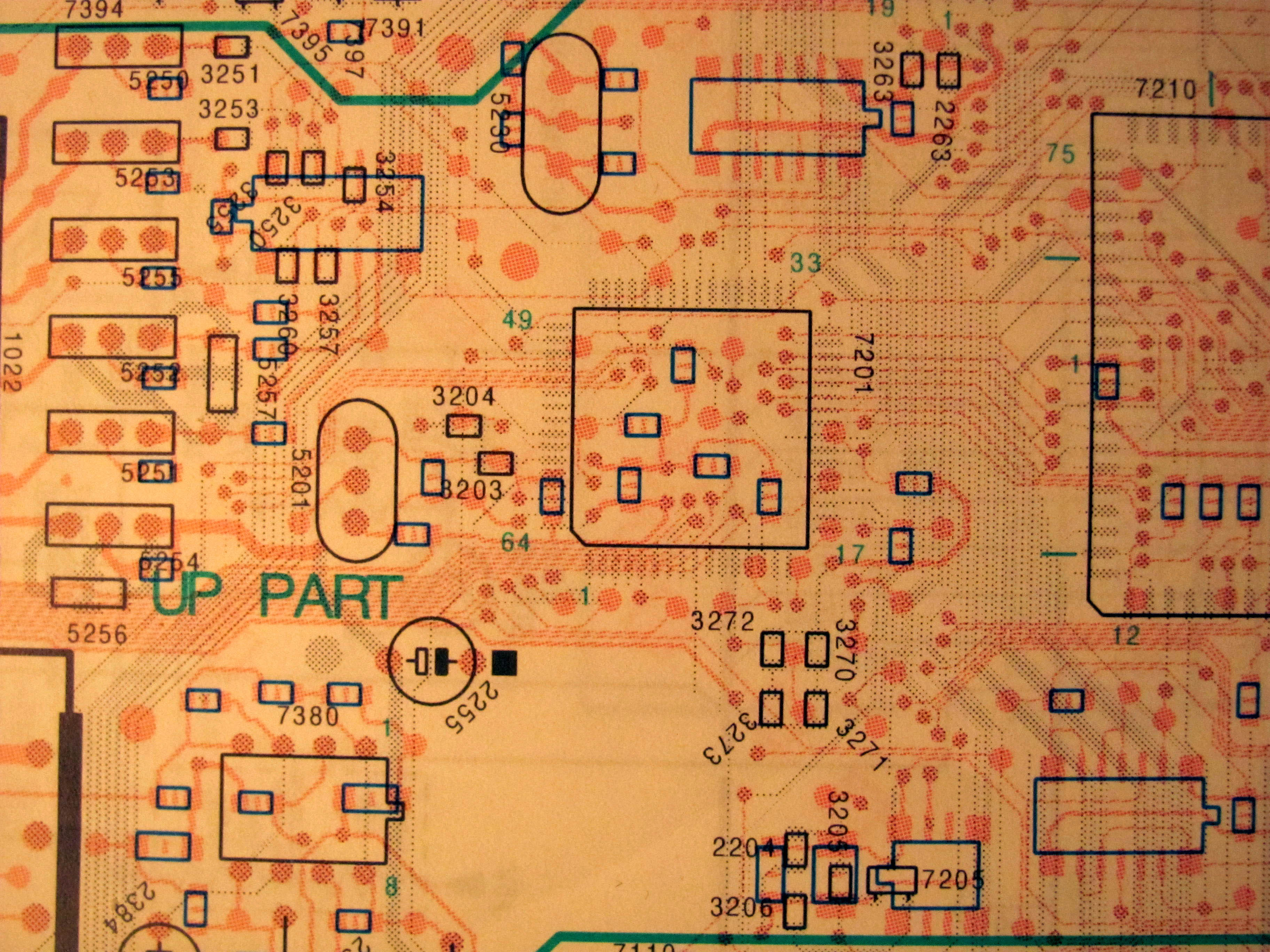
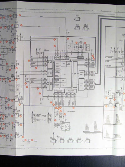
Corresponding board shot from the service manual.
After soldering

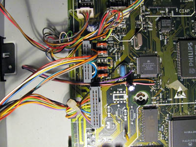
This is what it looks like after the soldering.
Brown and black are +5V and GND, respectively.
Pink is the 210/220 switch wire (GND for 210, +5V for 220).
Purple is the PAL/NTSC switch wire (GND for PAL, +5V for NTSC).
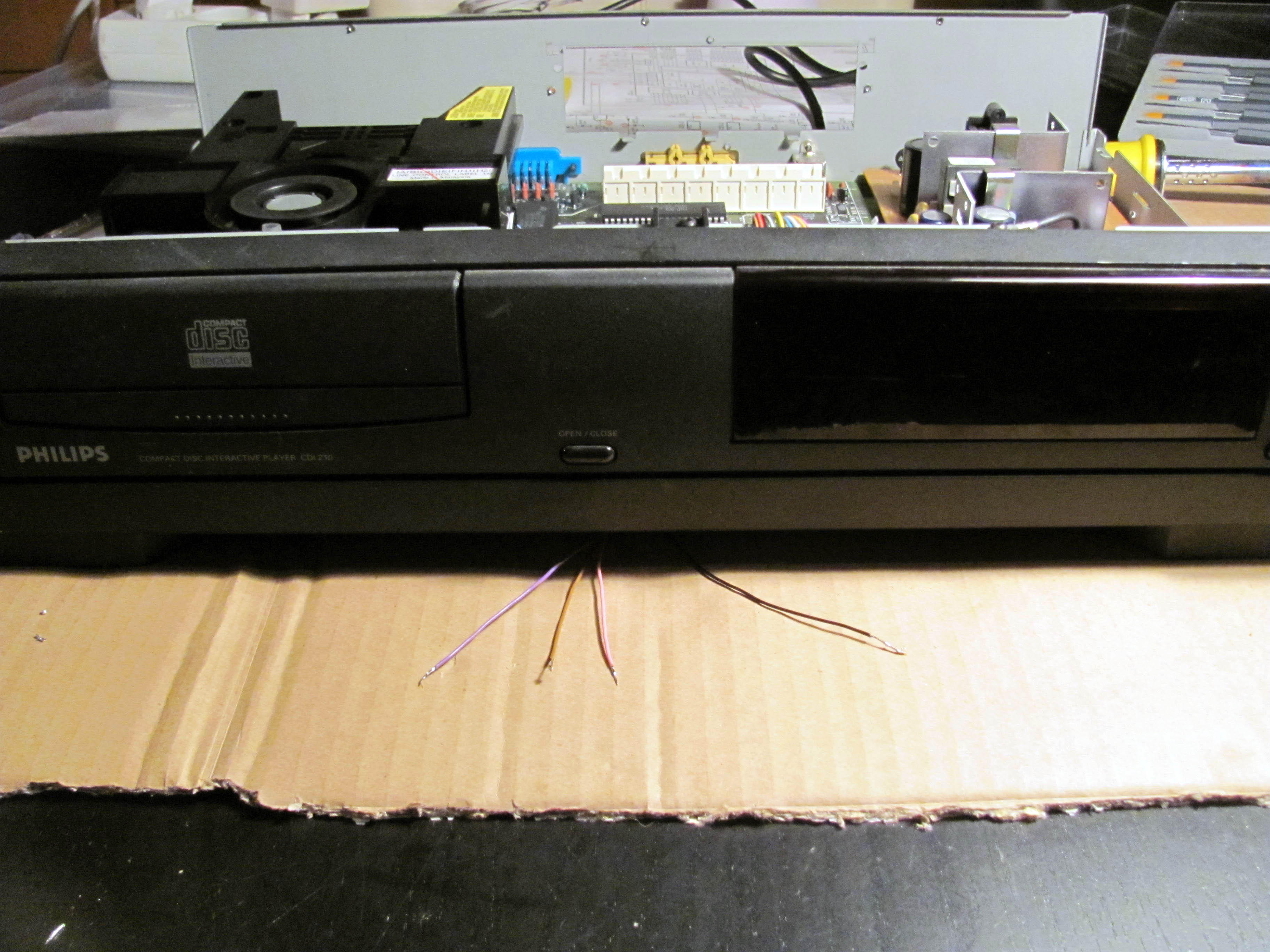
The new wires neatly fit through a hole in the bottom of the player...
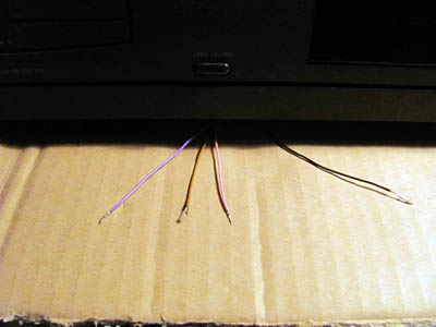
And they exit at the front of the player.

Here's a larger view.
Now we need to reinstall the plastic DVC encasing.
After that just press the DVC gently into it.
Reverse the procedure above for closing up the player.